| Stair Alignment
|
Sets the controlling anchor point for the stair.

Top
Left
|

Top Center
|

Top
Right
|

Middle
Left
|

Middle
Center
|
Middle
Right
|

Bottom
Left
|

Bottom
Center
|

Bottom
Right
|
|
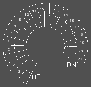
| Stair Terminology
|
- Base is the bottom of the stairs with direction
of travel going up
- Top is the top of the flight
of the stairs with direction of travel down.
- Center
is a stair alignment that uses the
walk line for placement
| Examples
|
Left Base alignment
|

Left Top alignment
|

Center Landing alignment
|
- Landing is an intermediate platform; the first
segment defining the starting (base) stair flight, with direction of travel
down from the landing, and the second segment defining the ending (top) stair
flight with direction of travel up from the landing.
Tip: Left/ Right alignments
help with placing stairs along walls.
|
| Stair Configurations
|
bbd provides predefined set of
stair configurations including common industry standard stair configurations.
Dynamic placement allows you to define unique stair configurations through
precise placement of stair and landing segments. The Preview on the placement
dialog displays the actively selected configuration.
Note: Winder stairs are designed to
adhere to the International Building Code, which follows 2 main requirements
for most stair types:
- The walk line is
the same length as the standard treads on the entire stair (measured 12" from
the edge in International Building Code). While the code allows for 3/8"
tolerance, that's usually a field construction tolerance, not a
drawing/modeling tolerance.
- The small side of
the winder tread meets a minimum dimension (6" in International Building Code)
Note: Spiral stairs are
designed with an uniform curved walk line keeping the minimum tread depth on
the inner curve. The tread depth and riser height on the line of travel are
maintained.
|
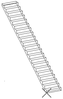
 Straight Stair Straight Stair
|
Constructs a floor to floor straight run of stairs with two data
points (start point and
direction).
The
start point defines the flight origin
(1), and the
direction point (2) along with the mouse
movements determines the direction of the run.
|
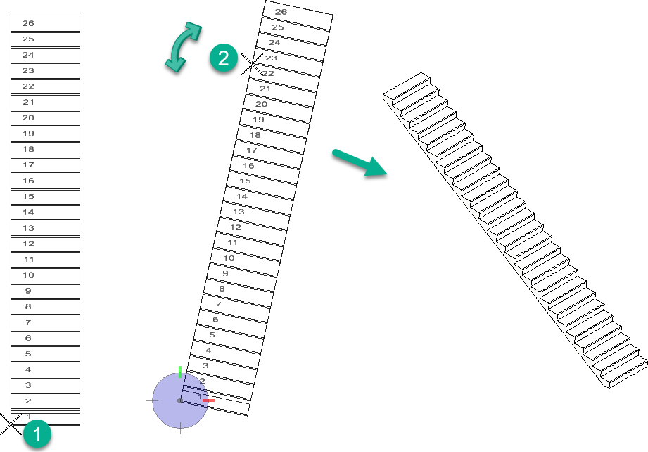
 Straight Stair with Two
Runs Straight Stair with Two
Runs
|
Constructs a straight run of stairs with an intermediate landing
with two data points (start point, and
landing point).
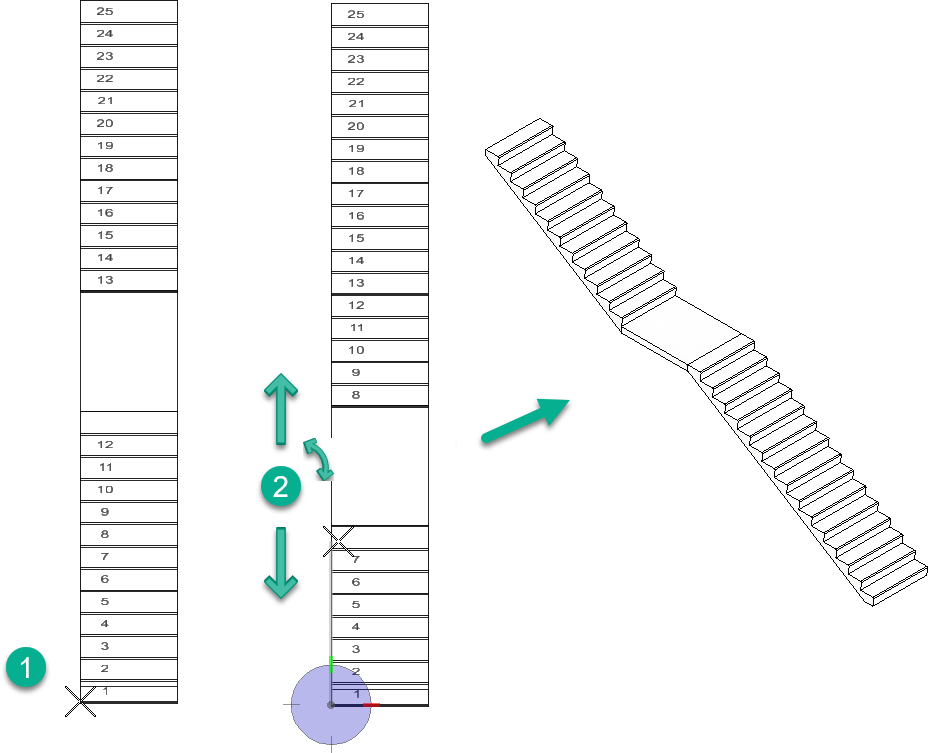
The
start point defines the flight origin
(1), and the
landing point (2) determines the landing
position and the direction of the run. This is done by moving the mouse over
the stairs to manipulate tread distribution in the runs.
|
 Quarter Turn Stair Quarter Turn Stair
|
Constructs a floor to floor quarter turn stair with
three data points (start point,
direction 1st run, and
direction 2nd run).

The
start point defines the flight origin
(1). The
direction 1st run point defines the
landing location; as you move the pointer, distributes the treads in the first
stair flight (2). The
direction 2nd run determines the angle
of the remaining stairs (3).
Note: For stairs with an even numbers of risers, the
start and end segments have an equal distribution of risers, whereas a stair
with an odd number of risers, the starting segment has an additional riser
compared to the ending stair run.
Tip: You can lock into a desired angle
with
AccuDraw. In the quarter turn the cursor
movement can orient the segment in 180° in the X–Y plane. The landing depth is
typically set to the stair width (W), plus one tread (T). However, it can be
modified (increased) using the
Heads Up Display dimension editor.
|
 Half Turn Stair Half Turn Stair
|
Places a floor to floor half turn stair with three
data points (start point,
1st landing point,
2nd landing point).

The
start point defines the flight origin
(1). The
1st landing point locates the landing
and distributes the treads accordingly in each segment (2). Moving the mouse
away from the origin, when defining the
2nd landing point flips the segment in
either direction (3). This orientation determines the direction of travel of
the legs of the stairs in clockwise or counterclockwise directions, and
determines the landing width.
Note: The half turn stair configuration resembles the
quarter turn, except the
2nd landing point controls the landing
width keeping the segment orientation unaltered.
Tip: The default distance between two segments is set
equal to the tread depth (T). Extending the cursor beyond 2W+T stretches the
landing width.
|
 Two Quarter Turn Stair Two Quarter Turn Stair
|
Places a floor to floor two quarter turn stair with
two landings with five data points (start point,
1st landing point,
direction 1,
2nd landing point, and
direction 2).
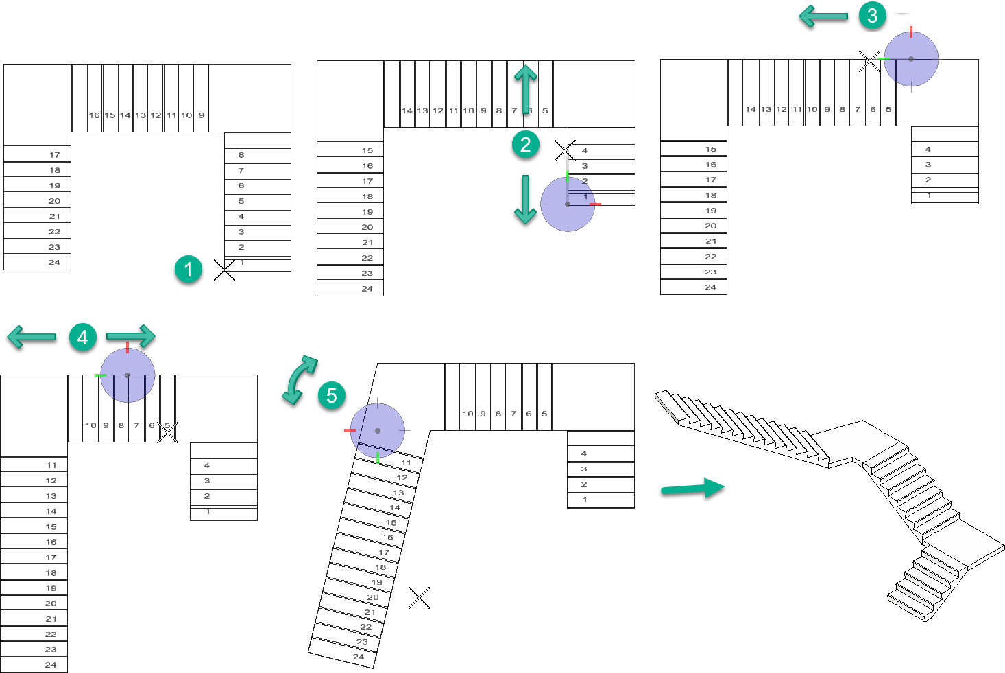
The
start point defines the flight origin
(1). The
1st landing point determines the
location of the first landing and tread distribution in the first stair run
(2). The
direction 1 point determines the
rotation of the remaining stair flights in a 180° range (3). The
2nd landing point determines the
location of the second landing and tread distribution in the second stair run
(4). The
direction 2 point determines the
rotation of the remaining stair flight in a 180° range (5).
|
 Three Quarter Turn Stair Three Quarter Turn Stair
|
Places a floor to floor three quarter turn stair
with two landings with seven data points (start point,
1st landing point,
direction 1,
2nd landing point,
direction 2,
3rd landing point,
direction 3).
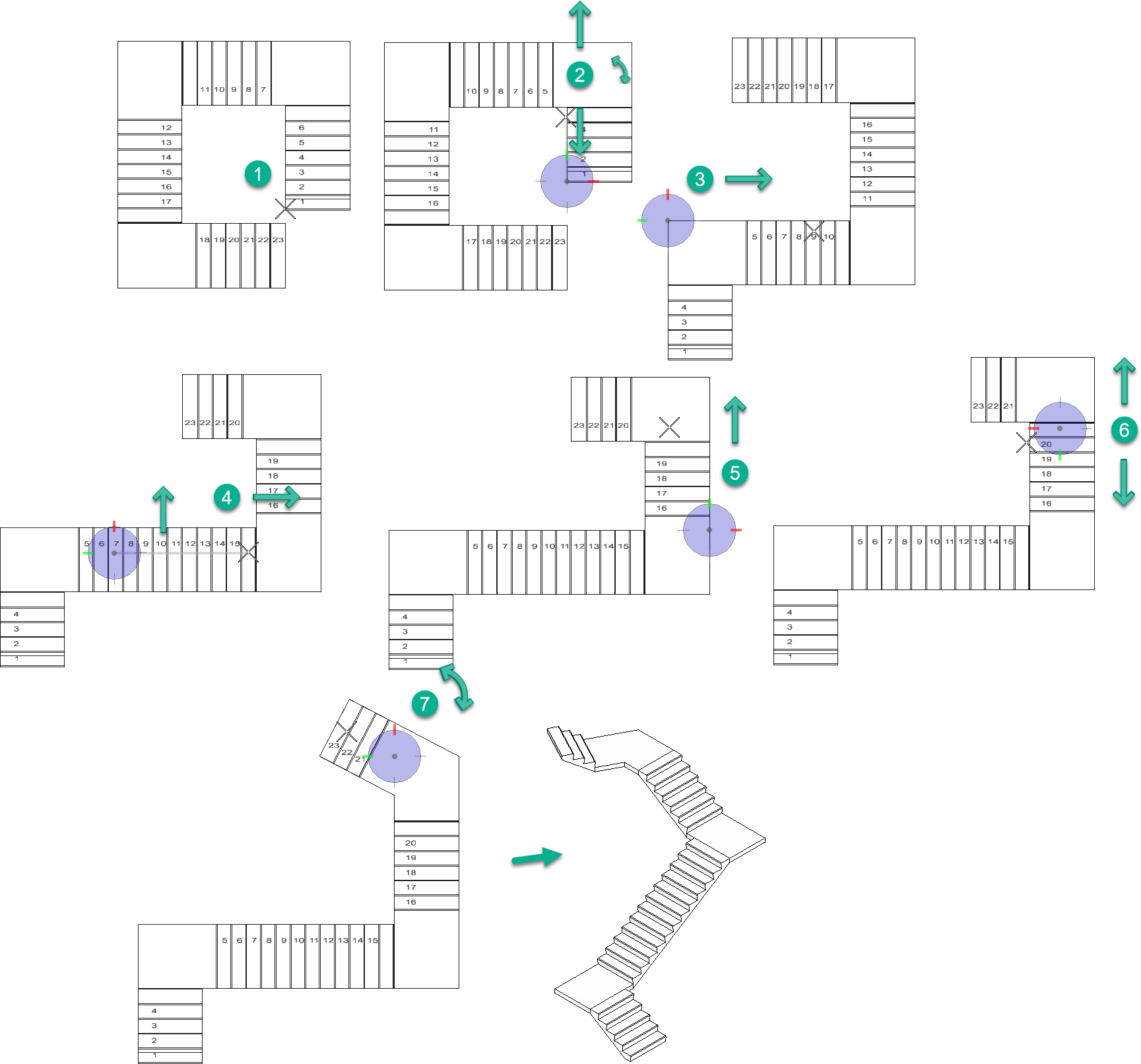
The
start point defines the flight origin
(1). The
1st landing point determines the
location of the first landing and tread distribution in the first stair run
(2). The
direction 1 point determines the
rotation of the remaining stair flights in a 180° range (3). The
2nd landing point determines the
location of the second landing and tread distribution in the second stair run
(4). The
direction 2 point determines the
rotation of the remaining stair flights in a 180° range (5). The
3rd landing point determines the
location of the third landing and tread distribution in the second stair run
(6). The
direction 1 point determines the
rotation of the remaining stair flights in a 180° range (7).
|
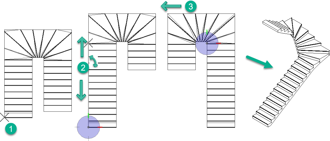
 Quarter Turn Winder Stair Quarter Turn Winder Stair
|
Places a quarter turn winder stair assembly with
three data points (start point,
flight 1 end, and
direction).
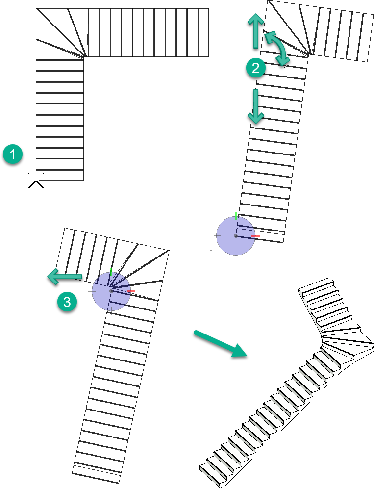
The
start point defines the flight origin
(1). The
flight 1 end point determines tread
distribution on the first stair run as well as its direction (2). The
direction point determines the angle of
the second stair run (3).
|
 Half Turn Winder Stair Half Turn Winder Stair
|
Places a half turn winder stair assembly with three
data points (start point,
flight 1 end, and
direction)
The
start point defines the flight origin
(1). The
flight 1 end point determines tread
distribution on the first stair run as well as its direction (2). The
direction point determines the angle of
the second stair run (3).
|
 Two Quarter Turn Winder
Stair Two Quarter Turn Winder
Stair
|
Places a two quarter turn winder stair assembly with
four data points (start point,
flight 1 end,
flight 2 end, and
direction)
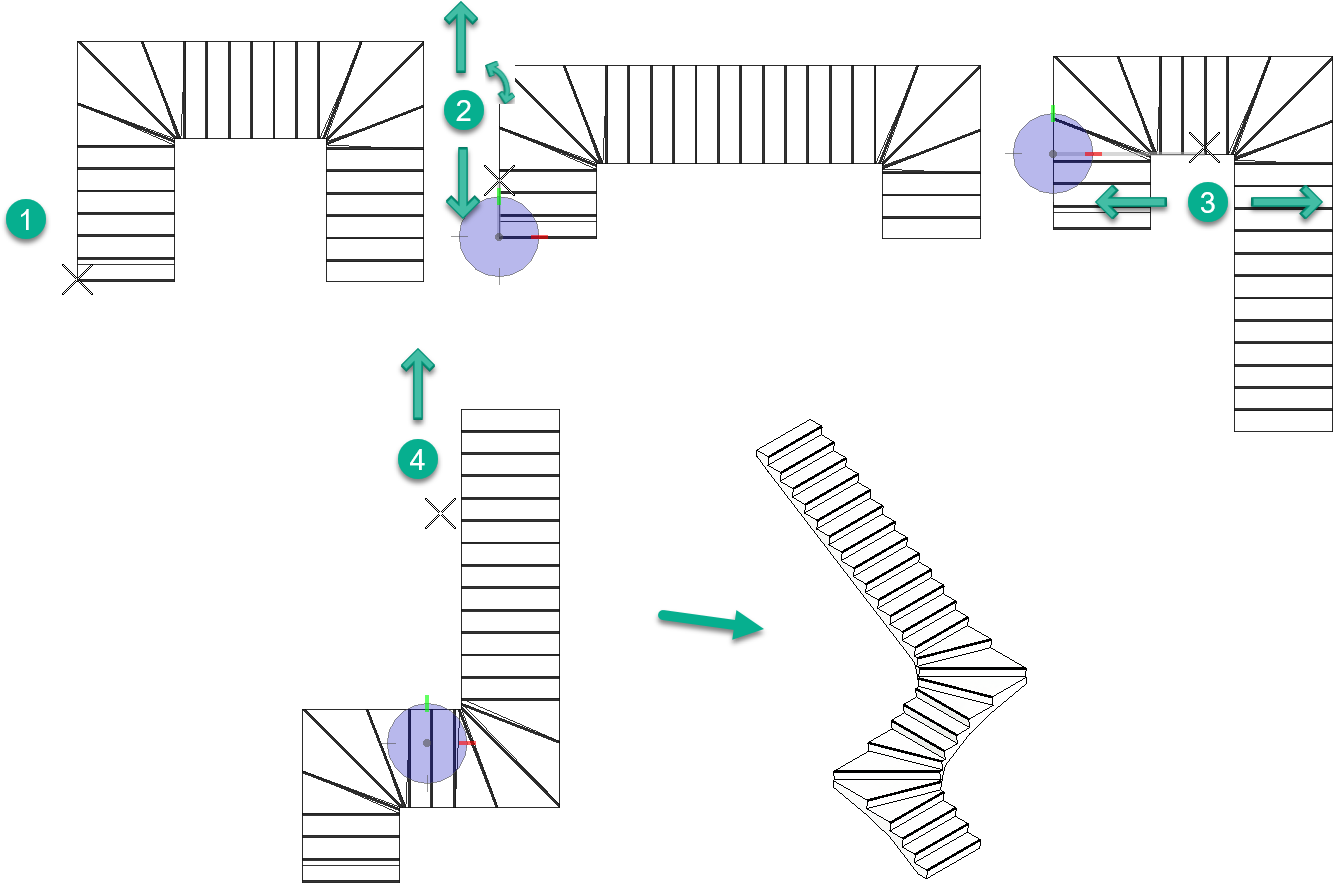
The
start point defines the flight origin
(1). The
flight 1 end point determines tread
distribution on the first stair run as well as its direction (2). The
flight 2 end point determines tread
distribution on the second stair run (3). The
direction point determines the angle of
the second stair run (4).
|
 Spiral Stair Spiral Stair
|
Places a spiral stair assembly with two data points
(start point and
direction).
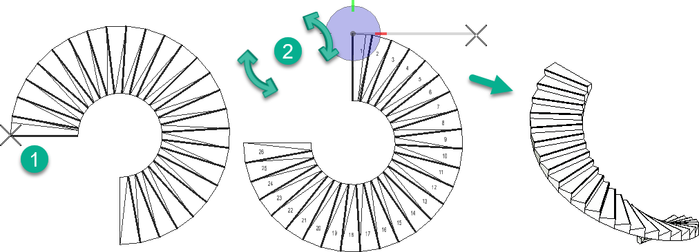
The
start point defines the flight origin
(1). The
direction point determines the overall
angle of the spiral stair (2).
|
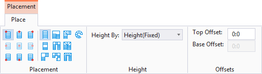
| Height By
|
Sets the method for defining the height of a flight
of stairs to one of the two options;
- Height
(Fixed) – Defines absolute height for a single flight of the stair
assembly.
- Floor
Constrained – Uses the floor definitions to determine the height of
the stair. The floor to floor distance of the currently active floor is taken
as stair height.
Tip: For
Floor Constrained height method you
must first select an activate floor in floor selector.
|
| Offsets
|
Note: For
Fixed Height stairs, depending upon the
stair alignment, one of the above
"Offset" options could be
set. Whereas, for height by
Floor Constraints stairs, both
"Offset" properties are
enabled. For example, for an active floor height of
15', setting the top offset to
2', and base offset to
1', results in a stair height of
16' (i.e. 15+2-1).
|
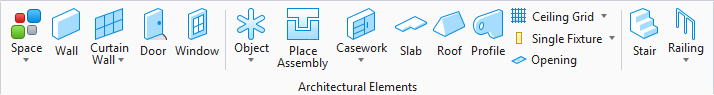
 Used to place a stair
assembly.
Used to place a stair
assembly.

 (
( (
( (
( (
( (
( (
( (
( (
( (
(


 (
( (
( (
(